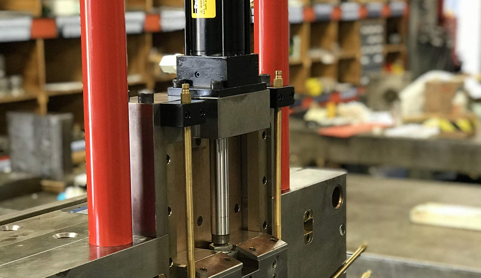
Hydraulic actuators are used for various injection molding applications such as: slides, core pulls, ejection systems, and unscrewing cores. In this article, we’ll explain each one of those applications and show how we’ve used them at Basilius.
Slides & Core Pulls
To remedy this issue you could use a hydraulically driven cam. In this video, you will see an animation of a project using both standard cam designs and a hydraulically driven cam.
(For more on this specific project, check out this post, where we break down the design in more detail).
EJECTION
In most injection molding applications, the mold is designed so the parts “stick” to the back half of the mold so that the molding machine can actuate the ejection system. However, there are cases where a part might be better suited to stay on the front half of the mold; in which case you could use a hydraulic-driven ejection system. The image below shows a mold we designed and built with a front-half ejection system. Because of the design of the part, gate location, and show surfaces, the only option (in this case) was to have a font-half ejection.
Unscrewing Systems
Unscrewing molds are most commonly driven by a spline or a rack and pinion system. Mechanical unscrewing cores are designed to function with the mold “open and close” movement, such that the mold open movement unthreads the coring from the plastic part. When the mold closes, the unscrewing core rotates back into place. This video shows a multi-cavity unscrewing mold driven by a spline system.
The limitation of this system is that the number of rotations is controlled by the distance the mold opens. For unscrewing mechanisms requiring several rotations, it may not be practical to us a spline system. For high thread count situations, a hydraulically driven rack may be the best option. The next video shows a rack and pinion style unscrewing system where a cylinder drives a rack to create the unscrewing mechanism.
Considerations
When designing and deploying a hydraulically driven mold there are a few important considerations:
- Control systems – The injection molding machine needs to control the hydraulic system. Most hydraulic molding machines will have connections for auxiliary control circuits. However, a hydraulic pump and control system could be required for fully electric molding machines.
- Sensors – Molding machines can control hydraulic systems by internal signals, external signals, or time.
- Internal Signals – Molding machines have internal signals for “mold open,” “mold closed,” “ejectors forward,” “ejectors returned,” etc. These signals can be used to trigger hydraulic cores.
- External Signals – Hydraulic systems often have forward and return sensors on the cylinder. These are tied to the molding machine/control system and are important for process optimization and error control. For example, a hydraulic core may need to be in the forward position in order for the mold to close. Having a signal to tell the molding machine the position of the cylinder allows the closing procedure to start immediately and ensures that the mold cannot crash.
- Time – Hydraulic systems can also use time delays where a specified amount of time passes before the hydraulic system actuates. The challenge with time delays is if a hydraulic system locks up at mid-stroke, the molding machine has no way of knowing and can crash the tool. Also, waiting for a timer to run out to start the next stage of the process can be a waste of cycle time.
- Locks – It’s important that when a mold closes, any moving components are locked into place because plastic pressure inside a mold during the filling and holding stages can be very high. Simply applying hydraulic pressure to a core may not be enough to resist the plastic pressure. In most cases, having a locking mechanism to hold coring in place prevents that movement.
- Torque & Pressure Considerations – Hydraulics systems can provide significant pressure and torque. Sizing for each application is essential, and making sure that each component in the system can handle the pressure is even more essential. It’s best to design systems so that the hydraulics are stopped internally by the cylinder rather than having a system with an end stop that has constant hydraulic pressure applied.


