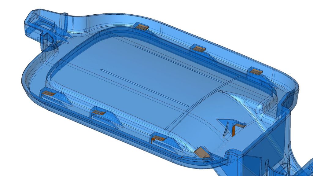
Figure 1.1 shows b-side of the part. We rendered the undercut faces in orange and made the part transparent. The most simple option to create these undercuts would be to core through the A-side of the part, so there are no actions. This was not an option because of cosmetics and design limitations. Also, using slide actions was not practical for these undercuts as they are on the inside of the part.
These types of small and hard to reach undercuts are great for lifters. With only a few more mold components, you can create undercut features. A few advantages are that lifters are compact and function with the ejection system. Lifters get some scrutiny for being unreliable, but good design practices should avoid these issues.

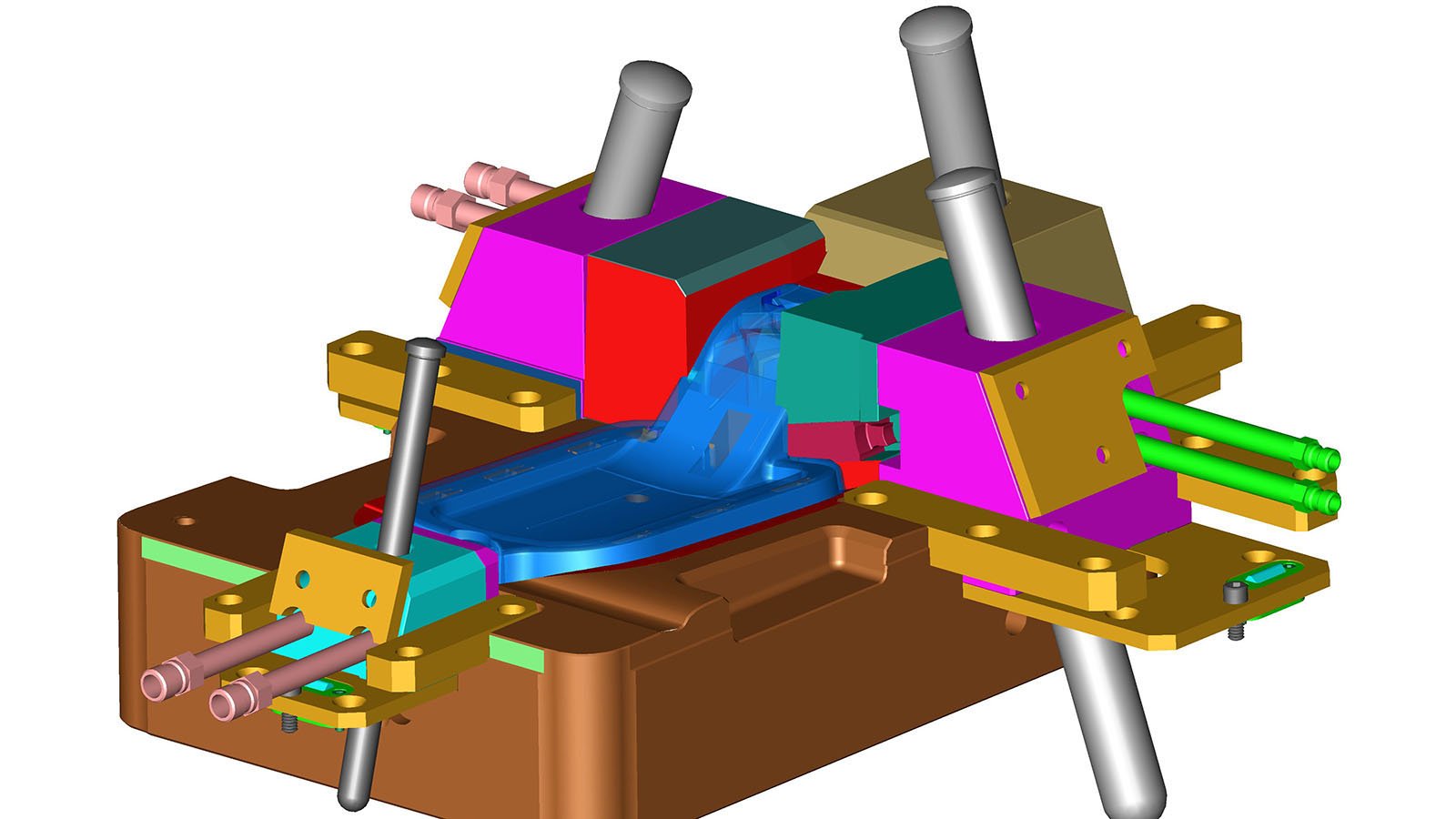
Three of the four slide actions are traditional horn pin and lock style. This is the default design for slide actions. It’s a simple system and a reliable way to remove an undercut. The video below is a simplified cut-away of how the horn pin and lock style slide functions.
The horn pin engages and disengages from an angled hole in the cam body. This makes the undercut retract when the mold opens and return when is closes. Additionally once the mold closes an angled backing (lock) ensures the slide seats. The lock is important for precision and resisting the plastic pressures. The forth cam required a delay coupled with an integrated lifter.
As you can see in the video below, the backside of a cam assembly starts retracting first as the mold opens. The lifter action connects to the backside of the cam and relieves a small undercut in the cam face. After the lifter and backside of the cam have cleared the undercut the main cam face moves back. The final movement of the entire assembly retracts the remaining components.


